VHP X USER INFORMATION & TECHNICAL DATA
The KAVENZ VHP X was developed to make you faster and you will experience a completely new level of riding. The kinematics are designed in such a way that you will exceed your own performance or at least be safer on the trails.
But before you get started, we would like to thank you for the trust you have placed in our up-andcoming brand and ask you to read these instructions carefully.
Please do not hesitate to contact us if you have any questions.
Yours sincerely,
Giacomo Grossehagenbrock & Luca Magnin ( KAVENZ )
P.S. We are always happy to receive feedback on how we can improve our products.
1. GENERAL INFO
This user manual is the most important element to prevent any damages and risks during the use and servicing of your frame. It is provided to give you the most important information on your bike frame and to give you helpful tips over the entire life of your frame. If you have any doubts or uncertainties regarding the work on your frame, you should always consult a qualified bicycle mechanic or the Kavenz service.
Please read this manual carefully before taking the first ride with your new frame and make sure you understand everything. Ensure that third-party users are also informed about the contents of these instructions and that they understand and observe the contents.
Keep this manual for future reference. If you sell or give away your frame, please also include this user manual.
This user manual is also available as a PDF below :
1. EXPLANATION OF SYMBOLS USED
2. TARGET GROUP
This manual is intended for you, the owner of the KAVENZ VHP X frame.
Basic knowledge of bicycle technology is a prerequisite for the assembly and maintenance of the bicycle. If in doubt, consult a qualified bicycle mechanic. Incorrect assembly or incorrect maintenance of your bike can lead to serious accidents with fatal consequences!
3. TOOLS
Work on the frame may only be carried out with suitable tools. Screw connections must be tightened to a defined torque using a torque wrench.
Correct assembly and disassembly of the components can only be guaranteed if the tools are in perfect working order and undamaged.
4. SELECTION OF COMPONENTS
The components must be selected taking into account the interfaces (see „4. Frame interfaces“), the intended use (see "3. Intended use“) and the maximum system weight (see "1.6. Maximum system weight“).
No child seats, child trailers or rear racks may be mounted on the frame.
5. WARRANTY AND GUARANTEE
For all information on warranties and guarantees, see www.kavenz.com.
6. MAXIMUM SYSTEM WEIGHT
The KAVENZ VHP frame is designed for a maximum system weight of 130 kg. The system weight is the sum of rider, bike, equipment (helmet, backpack, shoes, clothes) and luggage.
If components with a lower maximum system weight are mounted, the maximum system weight of the entire system is reduced to the value of the component with the lowest value.
7. WEAR PARTS
The bearings of the rear triangle, idler pulley and shock are wearing parts and should be checked regularly and replaced or serviced as required.
8. DISCLAIMER
The activities listed in this manual must be carried out by persons with sufficient specialist knowledge.
The user is liable for damage caused by:
- Misuse or any other use beyond the range of the intended use (see „3. Intended use“)
- Non-compliance with safety regulations
- Improper installation, repair and maintenance
- Use of unauthorized spare parts and accessories
If you are unsure or if problems occur, always consult the KAVENZ Service or a trained bicycle mechanic !
2. SAFETY
Following the instructions specified in this manual does not absolve the riders from their duty of care to ensure that their bike is always in good condition. If there are any questions consult a qualified bicycle mechanic or the KAVENZ Service. As it is impossible to foresee all situations or circumstances that may occur during riding, this user information does not guarantee the safe use of the bike under all conditions. There are risks associated with the use of bikes that cannot be predicted or avoided and are the sole responsibility of the rider.
If you are unsure or if problems occur, always consult the KAVENZ service or a trained bicycle mechanic!
3. INTENDED USE
The intended use of Bikes is divided into five different categories – ranging from the use on paved roads through to downhill or freeride use. The bicycles are to be used exclusively in accordance with their intended use. Otherwise, the user assumes responsibility.
The KAVENZ VHP X frame is designed for CATEGORY 5.
If the bike is to be used in accordance with the regulations of category 5, all components must also be approved for this category !
CATEGORY 1: USE ONLY ON PAVED ROADS
Category 1 includes all bikes and components that should only be used on paved roads. The wheels are always in contact with the ground.
CATEGORY 2: FOR USE ON AND OFF THE ROAD AND FOR DROPS OF UP TO 15 CM
Category 2 includes all bikes and components that can be used in conditions described under category 1, as well as on gravel roads and moderate trails. The wheels may not always be in contact with the ground. Drops are intended to be limited to 15 cm or less.
CATEGORY 3: FOR USE IN ROUGH TERRAIN AND FOR JUMPS OF UP TO 61 CM
Category 3 includes all bikes and components that can be used in conditions described under category 1 and 2, as well as on rough trails and rough and unpaved roads that require good cycling skills. Jumps and drops should not be higher than 61 cm.
CATEGORY 4: FOR USE IN ROUGH TERRAIN AND FOR JUMPS OF UP TO 122 CM
Category 4 includes all bikes and components that can be used in conditions described under categories 1, 2 and 3 as well as in very rough and partially blocked terrain with steep gradients and the associated higher speeds. Regular, moderate jumps by experienced riders are no problem for these bikes. However, regular and permanent use of the bikes on North Shore trails and in bike parks should be ruled out. These bikes should be checked for possible damage after every ride due to the heavier loads. Full-suspension bikes with medium suspension travel are typical for this category.
CATEGORY 5: EXTREME BIKING (DOWNHILL, FREERIDE, DIRT)
Category 5 includes all bikes and components that can be used in conditions described under categories 1, 2, 3 and 4 as well as in demanding, heavily blocked and extremely steep terrain, which can only be mastered by technically experienced and very well trained riders. In this category, big jumps are to be expected as well as intensive use in bike parks or on downhill tracks. With these bikes, it is essential that an intensive check for possible damage is carried out after every ride. Pre-damage can lead to failure at significantly lower further stresses. A regular replacement of safety-relevant components should also be considered. Wearing special protectors is strongly recommended.
4. FRAME INTERFACES
SUSPENSION SETUP
Configuration | Fork | Shock | Rear Travel | Mounting hardware |
Trail | 160-170mm travel | 185 x 55 mm | 154 mm | Included with the shock extender |
Enduro | 180mm travel | 205 x 65 mm | 177 mm | Included with the shock extender |
Downhill | 200mm travel | 225 x 75 mm | 200 mm | 30 x 8 mm |
HEADTUBE
ZS 56/56 with the following height :
Size | S | M | M-L | L | XL |
Head Tube height (mm) | 110 | 115 | 120 | 125 | 130 |
HEADSET
ZS56/28.6 · ZS56/40 (for tapered steerer tube)
REAR BRAKE
IS 2000 (Use IS 2000 +60 Adapter for 200mm Disc)
REAR WHEEL AXLE
148 mm (BOOST)
BOTTOM BRACKET
73mm BSA or Pinion Interface
CHAIN GUIDE
Guide for idler pulley enclosed
ISCG 05 adapter available separately (You will need the ISCG 05 Adapter V3)
CHAIN LINE
50-53.5 mm (Factory setting 53.5 mm reduces cross chaining for 55 mm Chain Rings)
WHEEL SIZE
29" front wheel and 29" or 27.5" rear wheel
TYRE WIDTH
Up to 29 x 2.6"
SEAT TUBE
Inner diameter : Ø31.6 mm with internal cable guiding
Outer diameter : Ø35 mm
Minimum insertion depth : 100 mm
Maximum insertion depth :
Size | S | M | ML | L | XL |
Seat Tube length (mm) | 395 | 395 | 410 | 425 | 440 |
Maximal insertion depth (mm) | 320 | 320 | 335 | 350 | 365 |
WATER BOTTLE
Up to 750 ml (Fidlock Ready)
IDLER PULLEY
16T N/W
BALL BEARING
Ø15 / 28 x 7 mm (S6902 LLU MAX)
PADAMELON
5. SETUP
SAG SETTING
The SAG is the amount by which the suspension deflects due to the rider's own weight. Below you will find the SAG values we recommend according to your setup :
TRAIL - 185 x 55 MM SHOCK
MX LOW
Shock setup | Rear travel | SAG rear wheel (mm) | SAG shock (mm) | SAG Shock (%) |
185 x 47.5 | 132 | 39.6 | 13.135 | 28% |
185 x 50 | 137 | 41.1 | 13.66 | 27% |
185 x 52.5 | 141 | 42.3 | 14.01 | 27% |
185 x 55 | 149 | 44.7 | 15.06 | 27% |
MX HIGH
Shock setup | Rear travel | SAG rear wheel (mm) | SAG shock (mm) | SAG Shock (%) |
185 x 47.5 | 137 | 41.1 | 12.8 | 27% |
185 x 50 | 142 | 42.6 | 13.295 | 27% |
185 x 52.5 | 147 | 44.1 | 13.79 | 26% |
185 x 55 | 154 | 46.2 | 14.45 | 26% |
29 LOW
Shock setup | Rear travel | SAG rear wheel (mm) | SAG shock (mm) | SAG Shock (%) |
185 x 47.5 | 133 | 39.9 | 13.14 | 28% |
185 x 50 | 138 | 41.4 | 13.48 | 27% |
185 x 52.5 | 143 | 42.9 | 14.17 | 27% |
185 x 55 | 150 | 45 | 14.87 | 27% |
29 HIGH
Shock setup | Rear travel | SAG rear wheel (mm) | SAG shock (mm) | SAG Shock (%) |
185 x 47.5 | 137 | 41.1 | 12.9 | 27% |
185 x 50 | 141 | 42.3 | 13.2 | 26% |
185 x 52.5 | 146 | 43.8 | 13.9 | 26% |
185 x 55 | 153 | 45.9 | 14.5 | 26% |
ENDURO - 205 x 65 MM SHOCK
MX LOW
Shock setup | Rear travel | SAG rear wheel (mm) | SAG shock (mm) | SAG Shock (%) |
205 x 57.5 | 156 | 46.8 | 15.76 | 27% |
205 x 60 | 161 | 48.3 | 16.12 | 27% |
205 x 62.5 | 165 | 49.5 | 16.65 | 27% |
205 x 65 | 173 | 51.9 | 17.54 | 27% |
MX HIGH
Shock setup | Rear travel | SAG rear wheel (mm) | SAG shock (mm) | SAG Shock (%) |
205 x 57.5 | 161 | 48.3 | 15.12 | 26% |
205 x 60 | 167 | 50.1 | 15.79 | 26% |
205 x 62.5 | 171 | 51.3 | 16.13 | 26% |
205 x 65 | 178 | 53.4 | 16.81 | 26% |
29 LOW
Shock setup | Rear travel | SAG rear wheel (mm) | SAG shock (mm) | SAG Shock (%) |
205 x 57.5 | 157 | 47.1 | 15.57 | 27% |
205 x 60 | 161 | 48.3 | 15.92 | 27% |
205 x 62.5 | 166 | 49.8 | 16.62 | 27% |
205 x 65 | 171 | 51.3 | 16.97 | 26% |
29 HIGH
Shock setup | Rear travel | SAG rear wheel (mm) | SAG shock (mm) | SAG Shock (%) |
205 x 57.5 | 161 | 48.3 | 15.2 | 26% |
205 x 60 | 165 | 49.5 | 15.7 | 26% |
205 x 62.5 | 170 | 51 | 16.2 | 26% |
205 x 65 | 176 | 52.8 | 16.9 | 26% |
DOWNHILL - 225 x 75 MM SHOCK
MX LOW
Shock setup | Rear travel | SAG rear wheel (mm) | SAG shock (mm) | SAG Shock (%) |
225 x 67.5 | 179 | 53.7 | 18.075 | 27% |
225 x 70 | 184 | 55.2 | 18.61 | 27% |
225 x 72.5 | 188 | 56.4 | 18.97 | 26% |
225 x 225 | 195 | 58.5 | 19.87 | 26% |
MX HIGH
Shock setup | Rear travel | SAG rear wheel (mm) | SAG shock (mm) | SAG Shock (%) |
225 x 67.5 | 185 | 55.5 | 17.49 | 26% |
225 x 70 | 189 | 56.7 | 18.17 | 26% |
225 x 72.5 | 194 | 58.2 | 18.52 | 26% |
225 x 75 | 201 | 60.3 | 19.21 | 26% |
29 LOW
Shock setup | Rear travel | SAG rear wheel (mm) | SAG shock (mm) | SAG Shock (%) |
225 x 67.5 | 180 | 54 | 18.03 | 27% |
225 x 70 | 184 | 55.2 | 18.39 | 26% |
225 x 72.5 | 189 | 56.7 | 19.1 | 26% |
225 x 75 | 193 | 57.9 | 19.46 | 26% |
29 HIGH
Shock setup | Rear travel | SAG rear wheel (mm) | SAG shock (mm) | SAG Shock (%) |
225 x 67.5 | 184 | 55.2 | 17.6 | 26% |
225 x 70 | 188 | 56.4 | 17.9 | 26% |
225 x 72.5 | 193 | 57.9 | 18.6 | 26% |
225 x 75 | 199 | 59.7 | 19.3 | 26% |
SPRING RATE
The spring rates provided in the tables below are recommendations based on a target of approximately 30% SAG.
These values are intended as a starting point and should not be considered as a fixed or perfect setting. Suspension setup is highly dependent on the rider, bike configuration, riding style, terrain, and personal preferences.
We recommend using these values as a baseline and carrying out your own tests to find the setup that provides the best balance of support, comfort, traction, and control for your riding.
TRAIL - 185 x 55 MM SHOCK
| Rider weight with riding gear (kg) | Spring rate LOW Progression (lbs/inch) | Spring rate HIGH Progression (lbs/inch) |
| 60 | 375-400 | 400-425 |
| 65 | 400-425 | 450 |
| 70 | 450 | 475-500 |
| 75 | 475-500 | 525 |
| 80 | 500-525 | 550 |
| 85 | 550 | 575-600 |
| 90 | 575-600 | 625 |
| 95 | 600-625 | 650-675 |
| 100 | 650 | 675-700 |
| 105 | 675 | 725 |
| 110 | 700-725 | 750-775 |
| 115 | 725-750 | 800 |
ENDURO - 205 x 65 MM SHOCK
| Rider weight with riding gear (kg) | Spring rate LOW Progression (lbs/inch) | Spring rate HIGH Progression (lbs/inch) |
| 60 | 325-350 | 350-375 |
| 65 | 350-375 | 375-400 |
| 70 | 400 | 425 |
| 75 | 425 | 450 |
| 80 | 450-475 | 475-500 |
| 85 | 475-500 | 500-525 |
| 90 | 500-525 | 525-550 |
| 95 | 525-550 | 575 |
| 100 | 550-575 | 600 |
| 105 | 575-600 | 625-650 |
| 110 | 600-625 | 650-675 |
| 115 | 650 | 675-700 |
DOWNHILL - 225 x 75 MM SHOCK
| Rider weight with riding gear (kg) | Spring rate LOW Progression (lbs/inch) | Spring rate HIGH Progression (lbs/inch) |
| 60 | 300 | 300 |
| 65 | 325 | 325-350 |
| 70 | 325-350 | 350-375 |
| 75 | 350-375 | 375-400 |
| 80 | 375-400 | 400-425 |
| 85 | 400-425 | 425-450 |
| 90 | 425-450 | 450-475 |
| 95 | 450-475 | 475-500 |
| 100 | 475-500 | 500-525 |
| 105 | 500-525 | 525-550 |
| 110 | 525-550 | 550-575 |
| 115 | 550-575 | 575-600 |
CHAIN LENGTHS
When using a SRAM Transmission drivetrain, the required chain length can be determined via the SRAM AXS app or at https://axs.sram.com/guides/chain/calculator. Our lower chain guide is required for use with the SRAM Transmission shift system on all models.
For all gearbox frames, we recommend using an 11-speed chain with the following length:
PINION
Dropout | Chain length (number of chain links) |
+0 | 104 |
+10 | 106 |
+20 | 108 |
+30 | 110 |
EFFIGEAR
Dropout | Chain length (number of chain links) |
+0 | 106 |
+10 | 108 |
+20 | 110 |
+30 | 112 |
6. MAINTENANCE
Regular maintenance and care is the only way to ensure that all parts of the bike function perfectly. The required maintenance and inspection activities must be carried out by a person with the necessary qualifications.
FRAME
Task | Interval |
Check the torques of the screw connections. Torque values, see „7. Torques“ | First time after 100km and then every 200km |
Visually inspect the frame for damage such as cracks or deformation, especially in the area of the lugs intersection with the carbon tubes. If you are unsure or if problems occur, always consult the KAVENZ service or a skilled bicycle mechanic! If damage is discovered, the frame must not be used any further. Contact the KAVENZ service immediately! | After each ride and after crash |
TIP – CREAKING NOISE
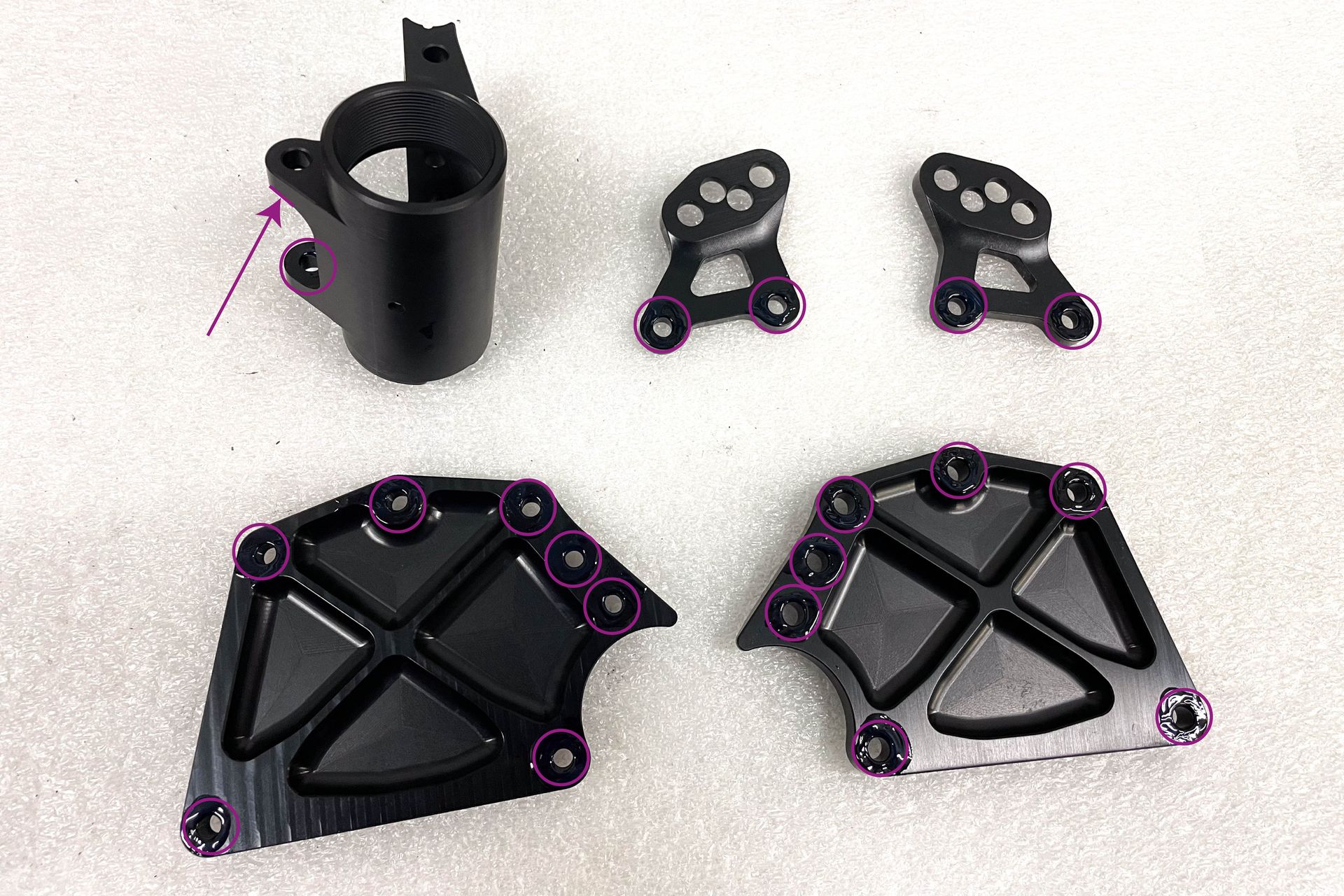
If creaking noises develop over time, remove the BB box and thoroughly clean all contact surfaces with isopropyl alcohol. Then, apply a small amount of medium-strength threadlocker (e.g. Loctite) to the contact areas shown below before reinstalling the BB box.
PINION GEARBOX
Task | Interval |
Change oil | 10 000 km |
Check the rollers of the chain tensioner and the chainrings for smooth running and wear | 500 km |
Open the switch box and clean and grease the pulley, sliding surfaces, switch box interior, planetary gears etc. | 500 km |
Check chain tension | 500 km |
Check shift cables for tension and ease of movement | 500 km |
Check all screw connections (except gearbox housing screws) | 500 km |
EFFIGEAR GEARBOX
Task | Interval |
Change oil | first time after 500 km subsequently annually |
COMPONENTS
The maintenance activities and intervals of the components must also be carried out according to the specifications of the respective manufacturer!
7. TORQUES
All nuts and bolts must be tightened with an appropriate torque wrench. Proper use prevents overtightening and breaking of the bolts.
DOWNLOAD THE BOLT CHECKLIST
MAIN FRAME
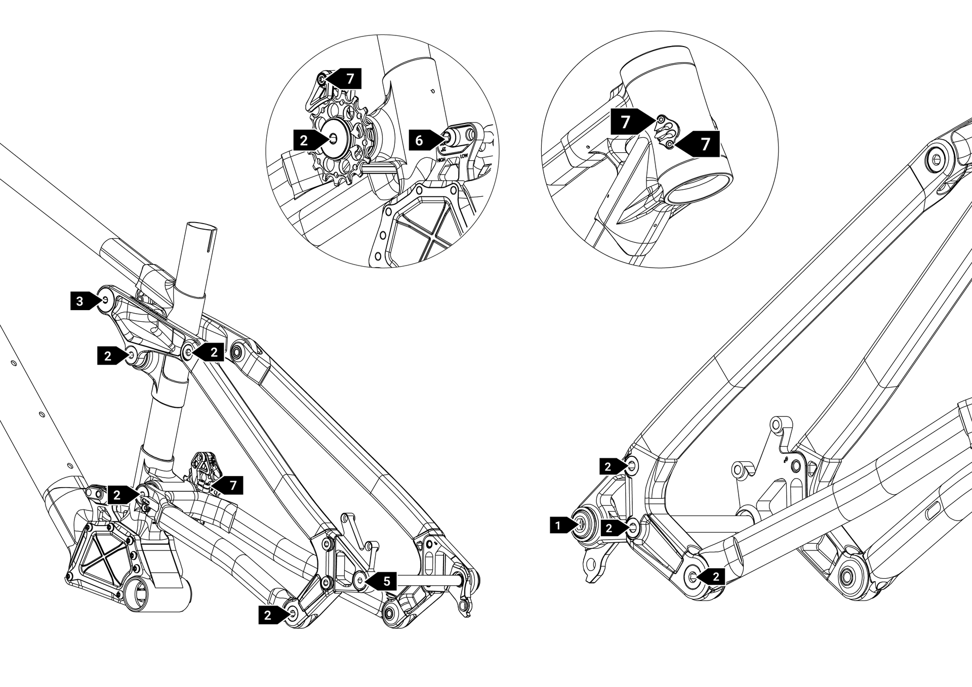
Position | Torque | Grease | Loctite 241/243 |
1 | 25Nm | ❌ | ❌ |
2 | 24Nm | ❌ | ✅ |
3 | 12Nm | ❌ | ✅ |
5 | 10Nm | ✅ | ❌ |
6 | 8Nm | ✅ | ❌ |
7 | 2-3Nm | ❌ | ❌ |
BB BSA 73 MM
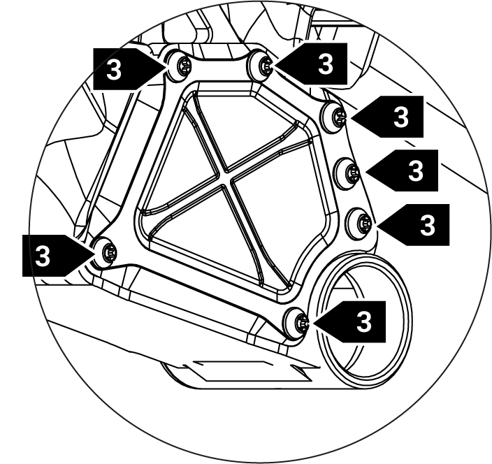
Position | Torque | Grease | Loctite 241/243 |
3 | 12Nm | ❌ | ✅ |
GEARBOX INTERFACE - Pinion Smartshift
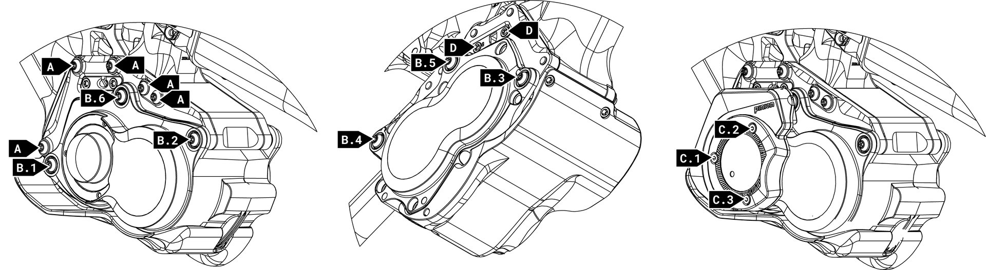
Position | Torque | Grease | Loctite 241/243 | Aditionnal info |
A | 12Nm | ❌ | ✅ | |
B | 10Nm | ❌ | ✅ | Tighten the retaining screws in the specified sequence |
C | 2-3Nm | ❌ | ❌ | Tighten the retaining screws in the specified sequence while rotating the shaft forwards |
D | 2-3 | ❌ | ✅ |
8. SPARE PARTS
Last update : 08.09.2026